RILYBOT 4: Motor Speed Input Adapter Plates
The motor speed input adapter plates allow an input to be used to read the value of one or two touch sensors and the speed of a motor through a single sensor input.
The speed of the motor can be read while the motor is running, but this adapter is mainly intended to read the speed of a motor that has been turned off with the Float() command, or even a motor that isn't connected to an output at all (thereby functioning only as a rotation input).
It works by placing resistors between the motor and the input sensor, both to protect against damage and to reduce the amplitude of the current induced by the motor on the input, which reduces the range of raw data values you see when reading the input. Then, the touch sensor (which is just an SPST switch) is wired in parallel through a much lower-value resistor. The result is that the input reading will fluctuate y a large value in response to the touch sensor, and added to this will be a smaller offset induced by the motor rotation.
Construction
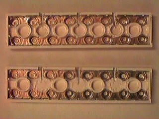
Start with a 2x8 conduting plate. On the underside there are two long strips of metal. These need to be cut in four places so it looks like this:
|
(In the photo, both plates are incomplete; in the bottom plate there is one cut yet to be performed.)
Also, some of the plastic must be removed to make room for the resistors. In the photo, the bottom plate has been altered by removing three circular "tube" features. A little more was done as needed.
Now notice the numbers: the four pieces of the top strip are terminals 1, 2, 3, and 4 and the bottom strip is 5 and 6. Each segment is two studs long except number 5 which is 6 studs long.
Connect the following resistors:
4.7K from 1 to 2
47.0K from 1 to 4
47.0K from 5 to 6
These three resistors are enough to read one touch-sensor input and the motor as a rotation sensor. If you want to read two touch sensors and a motor at once, you can add a fourth resistor:
10.0K from 1 to 3
In order to prevent short circuits and to make all the necessary connections fit, you will need to use some short lengths of wire.
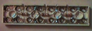
The result will end up looking a little bit like this:

This is a different multi-adapter
but note that this photo shows a different multi-adapter plate.
Connectons
Then, use the contacts 4+6 on the top of the adapter-plate to connect to a motor, for use as a rotation sensor input. This motor can also be connected to a motor output, by connecting the motor output to contacts 4+6 on the bottom of the adapter plate.
Connect the first touch sensor to contacts 2+5 on the top of the plate, and a second (if desired) to contacts 3+5, also on the top of the plate. Connect contacts 1+5 on the bottom of the plate to the sensor input.
If you wish, you can put the 2x8 conducting plate directly across the sensor and motor connectors on the RCX — this avoids the need for lots of extra connector cables and makes the overall design more compact. However, you will need to lift the adapter plate up by using 1x2 conducting plates. There are two reasons you need to do this: to prevent physically hitting the RCX's Power, View, Program and Run buttons, and to accommodate the fact that the motor and sensor connectors are not spaced the same distance apart as the 1+5 and 4+6 contacts on the adapter plate.
Usage from Software
Configure the input as a raw mode input. Each of the four switch combinations will create a different value (you should measure these to calibrate for your resistors; I got values around 900, 550, 350 and 250). The motor will add different amounts to the value depending on which touch sensors are pressed — from +-100 with neither touch sensor pressed to about +-25 with both touch sensors pressed.
| AA BBB CCCCC DDDDDDDDD | +---+---+-:-+-:-+---+-:-+---+---+---:---+-- 0 250 350 550 900 Legend: AA = range of readings seen when both touch sensors are pressed BB = range of readings seen when only the first touch sensor is pressed CC = range of readings seen when only the second touch sensor is pressed DD = range of readings seen when neither touch sensor is pressedRemember, if you want to use the motor as a passive sensor you have to stop it via the Float() command or its equivalent; if you use Off() the RCX just pins the motor voltage to 0 and the motor will be very hard to turn (since it is behaving as an active brake).
This page was written in the "embarrassingly readable" markup language RHTF, and was last updated on 2014 Dec 11.
 s.27
s.27