RILYBOT 4: How Does It Work?
Simplified Overview
In this simplified overview, a robot with only one input and only one degree of freedom of movement is "taught" to choose motion to the left or right depending on the level of illumination.
"Training" Mode
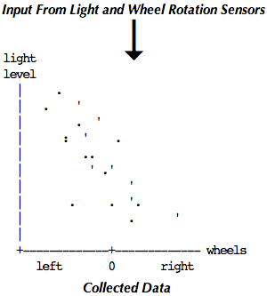
Robot continually reads its inputs, collecting data reflecting the relationship between its rate of movement and the ambient light level |
Analysis
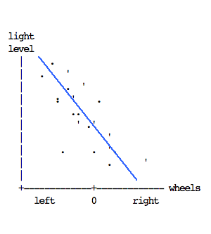
Robot uses statistics (e.g. linear regression) to model the correspondence between the two |
"Playback" Mode
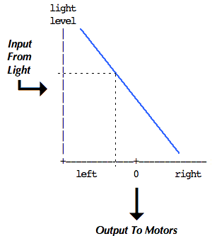
Robot continually reads the light input, derives the corresponding rate of movement, and moves the wheels accordingly |
As described further below, RILYBOT 4 actually implemented a 3×2 matrix of correlation parameters to control two outputs according to three inputs.
Chassis
The RILYBOT 4 chassis is a very simple and common chassis design. There are two wheels placed so the center of gravity is right between the two wheels, and small "skid pads" under the front and back edge of the chassis so it will slide easily at the third point of contact. If the robot is on a flat surface it will touch at three points: the two wheels and one of the skidpads (either front or back). The skid pads are placed so they almost touch the surface, to minimize the amount of "rocking" that takes place when the robot accelerates forwards or back. (Sorry, but I haven't had time to provide pictures. Any robot that fits the description in this paragraph should suffice.)
The chassis is held together with a number of horizontal and vertical cross-braces that make it difficult to fall apart on its own, or even to take apart deliberately. This is mainly for the purpose of being able to hit walls at high speed without damage to the robot.
The chassis is designed to allow fairly easy removal of the RCX to change batteries. This is accomplished by disconnecting the wires and the ends of four braces, then lifting the main body of the RCX up (leaving the bettery cover still attached to the chassis).
There are two bumpers (front and back) which can be hit either end-on or from a corner (diagonally). If the robot hits a wall at a very slight angle, it will drag a bit and turn a bit towards the wall, then activate the bumper. The current design does nothing to prevent the full force of the impact from being directed through the touch sensor's button.
Sensors and Wiring
There are two touch sensors (for the bumpers), a light sensor and a polarity switch (used as an input). In addition, the motors are used as crude rotation sensors. This is a total of six input devices, and they are wired to the RCX's three inputs through two special adapter bricks, which were custom-built for this project. The adapter bricks each contain three resistors, and allow voltage from the motors and two touch sensors to be read simultaneously through two of the inputs. The light sensor is connected through the polarity switch to the third input.
Software: User Interface
The RILYBOT 4 software has three modes: idle, training and go. When the program starts it is in idle mode. The polarity switch can be used to turn the light sensor on and off, which also causes a red light to go on and off. This light is useful for feedback.
training mode is entered by turning the light sensor on briefly, off again (within a second), and then on again. Training mode ends when the polarity switch is returned to center. go mode is entered by turning the light sensor on and leaving it on for over 1 second. idle mode is entered when the light sensor is turned off. Short beeps of different pitches are produced each time a mode change occurs.
In training mode, the robot starts clicking (much like a geiger counter) to indicate that it is collecting data. It gathers statistics on the sensor readings, the motor speeds, and their correlation to one another as described below in the software sections. It continues accumulating data until the light sensor is turned off. It also stops accumulating data if the data sum variables are about to overflow.
The sums are used to compute new trained speed and rotation values. Different values are used to keep track of speed and rotation in response to the different inputs (bumpers and light). If the light reading varied a significant amount during the training period, separate values of speed and rotation are stored for the lowest and highest light readings. Otherwise, a single value of speed and rotation is used.
The bumper speed and rotation values are updated only if the corresponding bumper was hit during the training; otherwise the previous values for that bumper are retained.
After computing and storing these learned values, it beeps and returns to idle mode.
In go mode, the robot beeps once and then starts monitoring the light and bumper sensors. Each of the three sensors produces a "stimulus speed and rotation" value, which is weighted (scaled) based on the stimulus' current "strength" and added. The bumper sensors have a strength proportional to e-t where t is the time since the bumper was last hit. The light sensor's strength is 1.0 minus the sum of the two bumpers' strengths, or 0 if this is negative.
The linear combination of speeds and rotations weighted by the sensor strengths produces one output speed value and one output rotation value. From these the desired motor speeds are computed and the motors are controlled via error diffusion
The speed and rotation are continually adjusted to reflect changes in the light level and the bumper stimuli. go mode ends when the light sensor is turned off; the robot then returns to idle mode.
Software Dataflow Model (Training Mode)
If you are familiar with dataflow programming techniques the following diagram should serve to explain the entire system:
input devices: Light Motor Motor Bumper Bumper B A C 1 3 : `. `. .' .' : `. `.' .' : `. .' `. .' multi-input : adapter adapter adapters : ,- brick 1 brick 3 -. : : : : V V raw sensor : Input Input readings: : 1 3 : : : : V V input task: : bounds checking, scaling, clipping : : : : : : V V V V separated : Motor Motor Bumper Bumper inputs: : A C 1 3 : : : : : : V V V V input tasks: : sum and difference decaying average : : `..' : : : : : .'`. : : : : :.' `.: : : : V V V V "cooked" : Surge Yaw Decayed Decayed inputs: : (A+C)/2 (A-C)/2 Bumper 1 Bumper 3 : : : : : : V V V V : +-----------------+ select dominant stimulus training - - >|3-way multiplexer| : main loop | |<- - - - - - - +-----------------+ : : : : : : V V V V V V accumulated SpeedL Speed1 Speed3 averages: RotL Rot1 Rot3Each of five inputs (two wheels via their motors, two touch sensors, and a light sensor) are separated and processed. (see the separate descriptions of the the adapter bricks and of decaying average).
The wheels are converted into surge (motion front-to-back) and yaw (rotation so as to point further left or right). The robot computes a statistical average of these two parameters, into three different sets of "accumulated average" variables depending on what is happening with the other three inputs.
The switches and light input are compared against each other to see which is "strongest". Touch sensors generate a "strong" input immediately after they are touched, and the signal then diminishes with time.
The "3-way multiplexer" selects which of the accumulated averages will be adjusted, accodring to which of those three inputs is currently strongest. Once a pair of accumulators is chosen, the current surge and yaw readings are added to that accumulator.
After some time (typically only 10-20 seconds) of data collection the robot is typically ready to be switched into "Playback" or "GO" mode, in which it will approximately imitate the behavior that was demonstrated to it.
Software Dataflow Model (GO Mode)
In this diagram, the first stages of bumper input are left out because they are the same as above.
input devices: Light (bumper input 0 same as above) : : : separated : (wheel speed Bumper Bumper inputs: : inputs ignored) 1 3 : : : : V V input tasks: : decaying average : : : ; V V "cooked" : Decayed Decayed inputs: : Bumper 1 Bumper 3 : : : learned : SpeedL Speed1 Speed3 : : values: : RotL Rot1 Rot3 : : : : : : : : : : : : V V V V V V : : : +-----------------+ : : go-mode - - >| weighted |<- - - - ' : main loop | average |< - - - - - - - - - ' +-----------------+ : : V V outputs Surge Yaw : : V V sum/diff task: sum and difference : `..' : : .'`. : :.' `.: V V motor speeds: Speed A Speed C (Spd+Rot) (Spd-Rot) : : V V motor control error-diffusion task: motor control : : V V outputs: Motor Motor A CAs before, the raw inputs are separated and processed. The light-level and decaying-average of the two touch sensors constitute the three inputs in GO mode (motors are now output-only).
A weighted average of all six accumulated averages is computed, using the strengths of the three inputs as the weights. The resulting surge and yaw are converted back to raw wheel speeds via sum and difference and passed to the motors.
Using Linear Regression
Linear Regression is not used in the current implementation. An approximation using one-dimensional averaging is used instead. See this description of linear regression as it applies to the RILYBOT 4 project.
Controlling the Motor Speeds
See the Floyd-Steinberg motor control page for a description of the technique used to control the motors.
This page was written in the "embarrassingly readable" markup language RHTF, and was last updated on 2014 Dec 11.
 s.27
s.27